MIG Welding
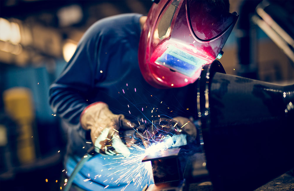
Arc MIG/MAG welding with continuous wire is a set of welding processes in which heat is generated by an arc striking between a fuse wire and the workpiece. The fuse wire performs the function of an electrode while simultaneously supplying material to the joint. That is, the passage of the current melts the wire, and the welder feeds the melted wire into the joint by applying heat with a torch. The welder continuously feeds more charged wire as needed to continue welding.
Welders must avoid contamination of the melting bath, which can lead to decreased weld integrity and increased post-weld cleanup costs. Protective measures include flowing gas from the torch (welding under gas protection) or using cored wire (welding without gas protection). Cored wire is also used for coated electrodes.
Transfer Pulsed Arc
Welding units with electronic controls can manage the continuous wire-welding process by modulating the current. Consequently, they can use special waveforms to achieve a smooth transfer of the metal, regardless of the heat supplied to the bath and the thermal contribution.
The waveform in Figure 1 represents the simplest form of welding with pulsed-arc transfer. When using simple wave forms, the welding unit modulates the electric current from a base value to a peak value. The base value is sufficient to keep the arc on. At peak level, a drop of melted wire detaches, forming the weld as it lands in the joint. The heat input factor is assessed based on the effective current, a value typically reported on the instrument, on the machine, or from the current clamp.
Pulsed-arc welding produces a penetration of the deposit directly timed with the peak current. As a result, the thermal contribution is lower as calculated on the effective current rather than base or peak values.

Pulsed-arc welding is frequently used to join thin metal sheets, especially when working with materials particularly sensitive to the thermal effects of welding (stainless steels, nonferrous alloys). Pulsed-arc welding reduces the risk of inclusions due to the peak current and overruns due to the reduced heat input, so it is often employed to weld light alloys. Pulsed-arc welding of aluminum has benefitted from the recent introduction of special programs related to the execution of the first pass, brazing, containment of welding fumes and noise, and averting the risk of increased porosity after welding.


WELDING PARAMETERS
Filler Materials
Weld quality is largely determined by choice of filler material. Unfortunately, over the years, welding wire has become increasingly poor, resulting in very low-quality welds. With lower-grade wire, the welding bead darkens and becomes contaminated by inclusions that are difficult to remove during the electrochemical cleaning process. The color of the wire used in welding also controls the coloring of the welding bead. If the wire has a dark color, even the welding bead will become dark. For these reasons, the wire production process plays a fundamental role. High-quality wire is obtained through a drawing process, a satin finish, and a double process of electrochemical pickling. The satin finish process is performed to lower the frictional resistance of the wire when it passes through the plastic duct during welding.
A double pickling of the wire increases production costs by 30% compared to the normal drawing process. Very often this last phase is left out to control costs, leaving the wire greasy from residues of the grain and lubricating oils used in the drawing process. During welding, these residues initiate a combustion process causing burns and darkening along the welding bead. The welding process involves the formation of silicates along the cord, making the subsequent electrochemical cleaning process very difficult.
Silicates that are created during the welding process result from the presence of silicon within the chemical composition of the filler material. The maximum amount of silicon permitted within the wire is 1%. Silicon is inserted between the alloying elements list because it can increase the wire’s flexibility and workability, thus increasing the drawing speed. These silicates cannot be removed from the cord but can be reduced during welding. Techniques to reduce the silicates include:
- Using a wire with a low percentage of silicon
- Decreasing the size of the welding bead
- Using a low-value electric current
Wires that contain a high percentage of silicon increase the probability of silicate deposits on the welding bead. This probability increases when the size of the welding bead increases. The concentration of silicate becomes very high, worsening the properties of the welded material when an unnecessarily high current is applied. The decision to increase the current is very often driven by a desire to speed up production. But this choice only leads to lower-quality individual welds and undermines the fidelity of the entire finished product.
Protective Gas
The amount of protective gas escaping from the nozzle is another important factor during the welding process. If the flow is too low, the gas does not protect the smelting bath adequately. Gas flow that is too high forms turbulence, which allows oxygen in the air to react with the melting bath and create unwanted oxides.

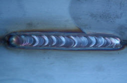
Improper gas flow causes a poorly formed welding bead whose shape is inconsistent and very prominent on the metal base. Groups of minute splinters made of filler material are visible (circled in red).
The inner diameter of the nozzle itself determines the gas flow rate. If the diameter is 15 mm, the flow will be 15 l/min. This flow rate is generally adequate to minimize splinters and prevent the formation of thick welding beads. Choose nozzle size based on the desired weld bead size: welding bead tight, narrow nozzle; welding bead wide, nozzle wide. The minimum gas flow rate required to perform a weld is 10 l/min.
The advantage of using oxygen as an active gas (MAG technology) is a reduction in the level of carbon when welding steels such as 304L and 316L. Previously, a gas mixture with 2% oxygen was used industry wide. But the welding resulted in a blackened cord that was resistant to the electrochemical cleaning process. Today, this mixture has been replaced by a carbon dioxide-based mixture. Numerous studies confirm carbon dioxide content of less than 5% does not alter the percentage of carbon in the welded steel. In addition, the active gas has a low temperature, enabling a weld with low heat input. The resulting bead is clear and homogeneous.
Special blends can be made by adding hydrogen. During welding, the hydrogen binds to oxygen present in the welding area and prevents the oxidation of the bead. The maximum percentage of hydrogen is 2% to prevent embrittlement and violent chemical reactions during welding. Hydrogen reduces the formation of silicates, creates a more stable melting bath, and reduces the time and expenses required in post-weld cleanup. These ternary mixtures are suitable to machine parts that have a thickness up to 4.5 mm. Binary mixtures produce almost identical results when used with parts that exceed 4.5mm.
Optimum sheet thickness is 1-2 mm. Sheet thickness affects the welding process because thick sheets have a higher silicon content than thin sheets.
Electric Parameters
Increasing the voltage raises the temperature of the weld pool, thus minimizing the formation of splinters. In the hands of an operator sufficiently skilled to follow the weld quickly, welds at higher voltage become impeccable because the weld pool cools quickly.
The following formula is used to calculate the H heat input based on voltage.

- V is the arc voltage (Volt)
- I is the arc current (Ampere)
- ¿ is the efficiency of heat transfer between the arc and the welding bath
- v is the feed rate of the torch
With increased running speed, heat input decreases. Figure 4 shows how a higher welding speed produces a more restricted section and a lighter color with fewer inclusions. Figure 4 shows how a higher welding speed produces a more restricted section and a lighter color with fewer inclusions.
Effect of welding speed on the weld bead
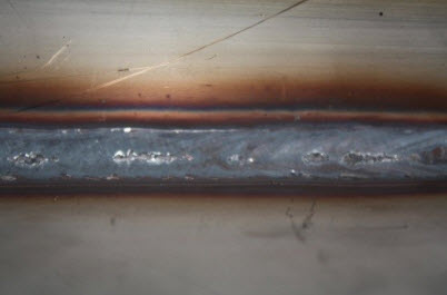
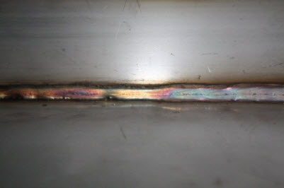
If the welding speed is too slow to lower the heat input, the value of the current decreases. Generally, an increase in the voltage achieves a good weld and avoids projections and splashing. A lower current decreases the heat input, leading to the formation of silicates and burns as shown in Figure 5.


Figure 6 Clear, homogeneous and well-relaxed welding bead created with pulsed-arc mode and optimum electrical parameters

Sprays that cover the base metal are often used to avoid the formation of spatter. But this option worsens the quality of the weld because the technique introduces a substance that causes a combustion reaction during welding, especially when using the pulsed-arc mode. The better choice is to use electrical parameters correctly matched with the gas flow rate, avoiding a cord that is dark, marred with inclusions and splashes, and somewhat flattened.


Compared to pulsed arc, MIG standard welding produces darkened and raised welding beards marred by many projections and oxide inclusions. These problems are accentuated as the distance of the edges is reduced.


For larger widths, flaps should be welded in the spray-arc mode (MIG high current), with care taken to ensure the feed rate is high. Doing so generates the correct heat input and reduces projections, which is an important consideration since this mode reaches a value of 220-230 amperes. Normally, using automatic systems can help avoid these problems.
Angle Torch
A welding performed in a nonoptimal way may generate a “glued” cord. In this case, the welding beard partially melts the base metal and hovers above the flaps welding. As a result, the part can become subjected to a mechanical action leading to the destruction of the welding board and eventually the disjunction of the two edges. A triangular weld bead with angles of 45° should be placed perpendicularly between two plates.
In MIG/MAG/TIG, the angle of the torch with respect to the direction of travel has a significant influence on the shape of the welding bath and the penetration level that can be achieved.
Figure 9: Different angles of the torch
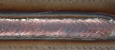

The torch can be positioned either perpendicular to the workpiece or at an angle. At constant welding speed, tilting the torch produces a homogenous and clear welding bead. Holding the torch perpendicular creates a darker weld bead and widens the heat-affected zone.
When the operator tilts the torch in the direction opposite to welding direction (pull technique), the energy of the arc is concentrated on the melting bath, producing greater penetration, a more stable arc, and less spatter than if it had been tilted toward the welding direction. Tilting in the opposite direction of the weld interferes with the visibility of the bath, but at around 25° (flat welding), the bath usually achieves maximum depth.
When the torch is oriented in the direction of advance (push technique), the melting bath becomes more concave with lower penetration and dilution. But the bath is easily visible and colder, and therefore more controllable.
The push technique is preferable in manual applications, with angles between 5° and 15° to lower the risk of operational defects. However, the push technique cannot be used with cored wires that produce slag. The intrusion of slag between electrode bath welds would cause the extinguishing of the arc. The torch angle allows the residual impurity to burn before the molten bath reaches the affected area so the residues are not incorporated into the weld itself. The clear appearance of the welding bead in the MIG/MAG mode exists only when, for a given set of correct parameters, the welding is at an internal angle. In this situation, the protective gas is not dispersed but remains concentrated on the work area.


